LDV
LDV Profile Sensor
Using conventional LDV systems in strong velocity gradients is difficult, because the measured velocity is averaged over the length of the measuring volume. The spatial resolution required for resolving boundary layer is about 1-10 µm, which cannot be fulfilled even by the shortest available focal length. Therefore, ILA GmbH developed a new LDV-profile sensor in cooperation with OPTOLUTION and the Technical University of Dresden (Prof. Jürgen Czarske*, Dr. Lars Büttner*) that offers a spatial resolution of 1% of the measurement volume length.
The basic idea of the developed LDV-profile sensor is to detect the position of the particle inside the measuring volume. This is realized by the overlap of two measuring volumes featuring different wavelength. One measuring volume offers a divergent fringe system the other a convergent one (Fig.3). The ratio of the detected Doppler frequency of both fringe systems fD1/fD2 is used to calculate the particle position z inside the measuring volume. The calculation is based on a calibration of the spatial varying fringe distance ratios.
Fig. 2 shows the comparison between a conventional LDV (red dots) and a LDV-profile sensor (small blue dots) measurement inside a free jet. The free jet has a diameter of 1mm. The length of the measurement volume of the conventional LDV (f=160mm) is about 500µm. The LDV profile sensor offers a length of the measuring volume of 1mm with a spatial resolution of 1% (10µm). It is obvious that the conventional LDV system is not able to resolve the high velocity gradient in the shear stress region of the free jet.
*„Czarske, J., Büttner, L., Razik, T., & Müller, H. (2002). Boundary layer velocity measurements by a laser Doppler profile sensor with micrometre spatial resolution. Measurement Science and Technology, 13(12), 1979-1989 ,https://doi.org/10.1007/s00348-021-03148-0”
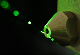
Fig. 1: Measuring volume of a profile sensor inside a free jet
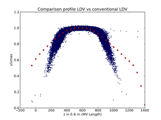
Fig. 2: Comparison of the measurement in a jet flow with a profile sensor and a conventional LDV
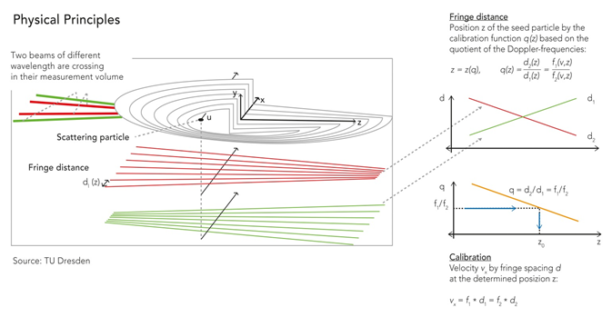
Fig. 3: Measuring principle of a profile sensor
LDV Profile Sensor Shift
Velocity profiles in boundary layers are characterized by strong velocity gradients, high dynamic velocity ranges and strong optical reflections. Profile Sensors are the appropriate technique for near wall measurements due to their good spatial and velocity resolution.
In case of boundary layer measurements the velocity increases rapidly inside the measuring volume from zero at the wall to high values in the main flow. The application of a frequency shift to one of the laser beams enables the separation of the signal from the envelop by digital or analogue filtering. Therefore, it is possible to detect negative velocity components for instance inside a region of separated flow. The idea to combine high spatial resolution with flow direction detection led to the development of the shifted version of the Profile Sensor.
The Profile Sensor Shift is constructed by the expansion of the ILA standard 1D- or 2D-LDV-Probe with an additional velocity component. All components are fixed in one casing and mounted on the same optical axis, therefore the handling of the probe remains easy and the requirements for the optical access to the flow are minimal.
The Profile Sensor Shift is configured by four laser beams in one plane, effectively superimposing a diverging and a converging fringe pattern in the measurement volume. Optionally the additional vertical velocity component can be measured by the third beam pair (Fig.4). The accurate positioning of the measurement volume relative to the boundary layer is realized by a compact traversing system (Fig. 5).
The shifted profile sensor can be equipped with a focal length between 150mm and 500mm (800mm). Lower focal length leads to higher spatial resolution. Depending on the applied focal length, spatial resolutions of the measured velocity profile down to a few µm are feasible.
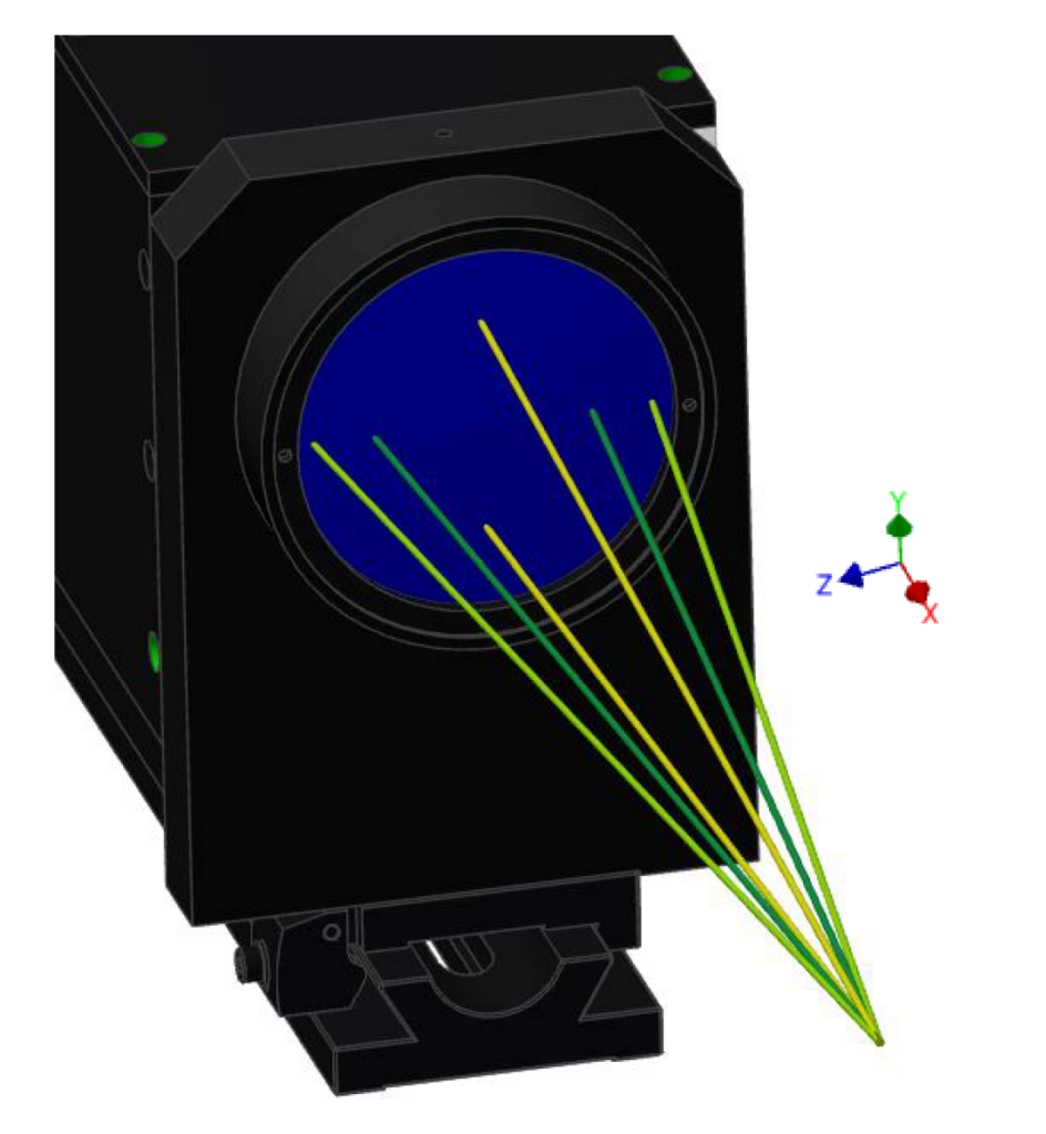
Fig. 4: 2D LDV Profile Sensor Shift with six beams
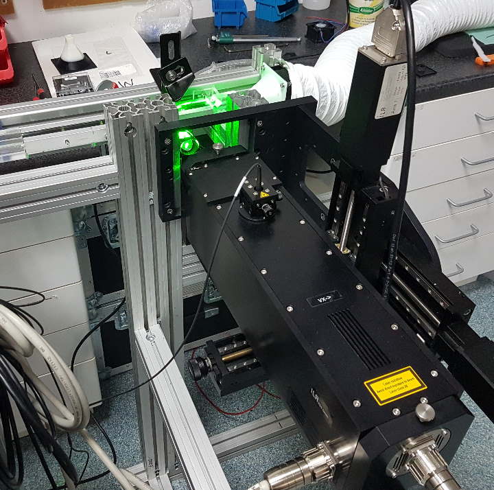
Fig. 5: LDV Profile Sensor Shift with traversing modul
Application Boundary Layer
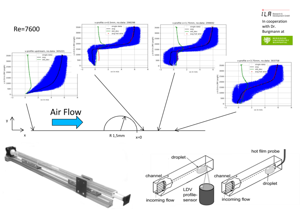
Measurements in a small wind tunnel [w=15mm, h=10mm] demonstrate the potential of the “Shift Profile Sensor” for fundamental and industrial investigations of boundary layers. An axial velocity profile in the boundary layer for air flow in the rectangular cross-section has been obtained, including the viscous sublayer at y+ values < 1. The point closest to the wall at y+=0.23 has a wall distance of ≈10 µm. Data for the following plot in Fig. 6 is taken from https://doi.org/10.1007/s00348-021-03148-0 .
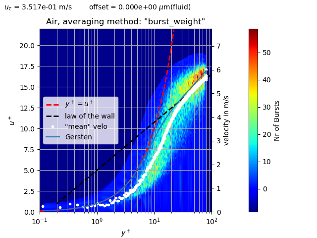
Fig. 6: Normalized flow profile in the viscous sub layer
Application Separated Flow
The profile sensor was also used to characterise the separated flow behind a droplet, compare Fig. 7. An excellent agreement between the shift Profile Sensor and conventional hot wire measurements in the region without backflow can be observed. However, the negative velocities in the wake region can only be captured by the shifted Profile Sensor.