PDA
Measuring Principle of Phase Doppler Anemometry (PDA)
The principle of PDA measuring is related to the LDV measurement method which uses two intersecting laser beams, generating an overlapping region, which is known as measurement volume (MV). A pattern of interference fringes is created in the MV, where the distance between the interference fringes is defined by the wavelength of the laser light and the angle between the two laser beams. Particles present in the flow scatter the laser light at a frequency proportional to the flow velocity when passing through the MV. This scattered light is transformed into a current signal by the PDA photo-detectors, then amplified and converted to a voltage signal in the PDA Controller. The frequency shift of the scattered light by the Doppler-effect is used to determine the velocity of the particle.
The PDA Receiving Optic is easy to use and can simultaneously measure the velocity of the particles and the particle size. No laser is included in the Receiving Optic itself. An additional LDV Probe is therefore required for operation. Since particle size determination does not require a calibration factor, the accuracy is maintained and does not need to be recalibrated.
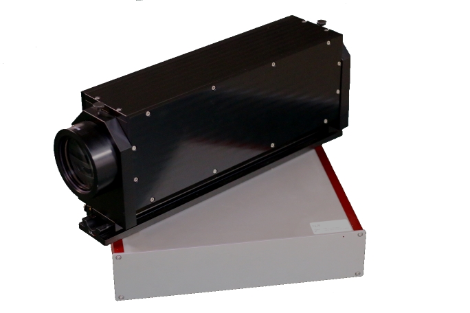
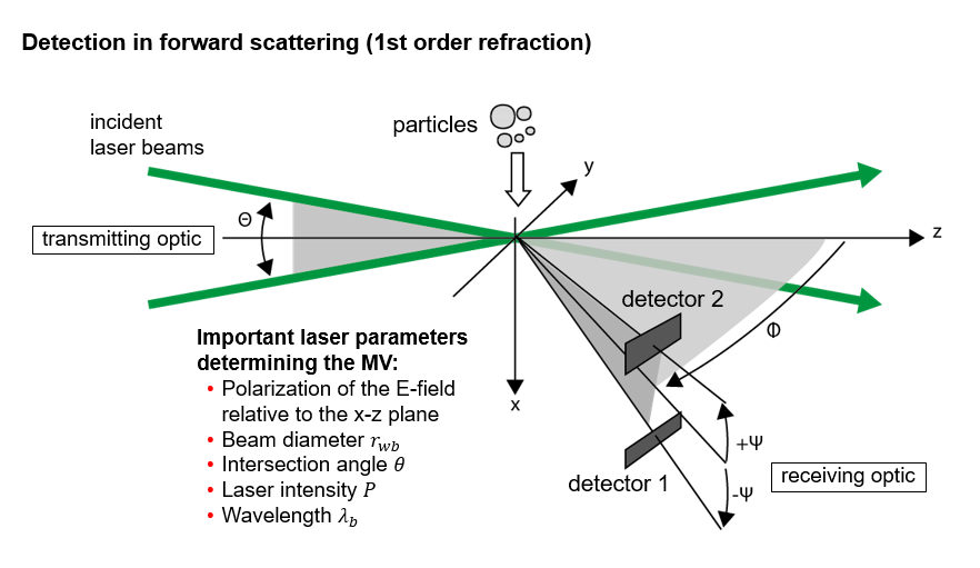
Fig. 1: Measurement principle of PDA (based on source: WSA RWTH Aachen)
For measuring the particle size the scattered light generated by the 1st order refraction of the incident laser beam in the droplet or particle hits the receiving lens of the PDA Receiving Optic (see Figure 1) and is slipped into its photo-detectors. For the measurement of particle diameters usually two detectors would be sufficient. By using a third detector, the phase jump at >360° can be used to achieve a coarse and a fine resolution of the phase difference measurement. Taken together, they are intended to prevent the 2π ambiguity caused by the phase jump of larger particles. This means that a phase shift of more than 360°, e. g. 370°, is not recognized as 370°, but as 10°, thus creating ambiguity.
Therefore, the light is cut into three parts with equal areas by the aperture mask (see Figure 2), spatially filtered by a pinhole, and each part is received by a single photo-detector. Due to the different scattering angle with which each detector receives the light, the phase of the light wave is different. There is a correlation between the difference of the phases between the photo-detectors and the diameter of the particle by which it can then be calculated.
For the calculation of the light, a factor must be known. It depends on the focal lengths of the transmitting and receiving optics, the laser frequency, the angle of intersection of the laser beams and the refractive index of the particles. Different working distances are possible by using receiving lenses of different focal length. However, this changes the viewing angle of the detectors and thus the phase difference and maximum particle size for a measurement. The receiving lens is mounted in a holder, which can be easily interchanged for one with a different focal length. The PDA aperture mask is located behind the receiving lens.
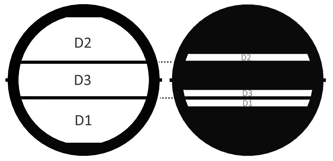
Fig. 2: PDA aperture masks for different particle size ranges
The PDA Receiving Optic and the LDV Probe are arranged at a fixed angle to each other, on which the phase to diameter factors depend (see example in Figure 3). This has a direct impact on the measurement accuracy. The light scattered by the particles inside the measuring volume is collected forwards, or under the fixed angle, by the receiving lens of the PDA Receiving Optic. All optical elements are aligned and rigidly fixed inside. This and the robust mechanical and optical design guarantee high system stability and a high measuring accuracy.
For further information about the principles of PDA we recommend reading “Laser Doppler and Phase Doppler Measurement Techniques” by Albrecht et al.
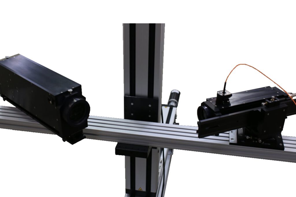
Fig. 3: Measuring setup of PDA and LDV on Traversing System
Phase Doppler Profile Sensor (PDPS)
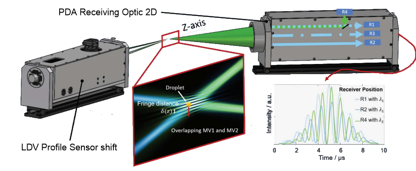
Fig. 4: Measuring principle setup of PDA Receiving Optic 2D with LDV Profile Sensor shift
(based on source: WSA RWTH Aachen)
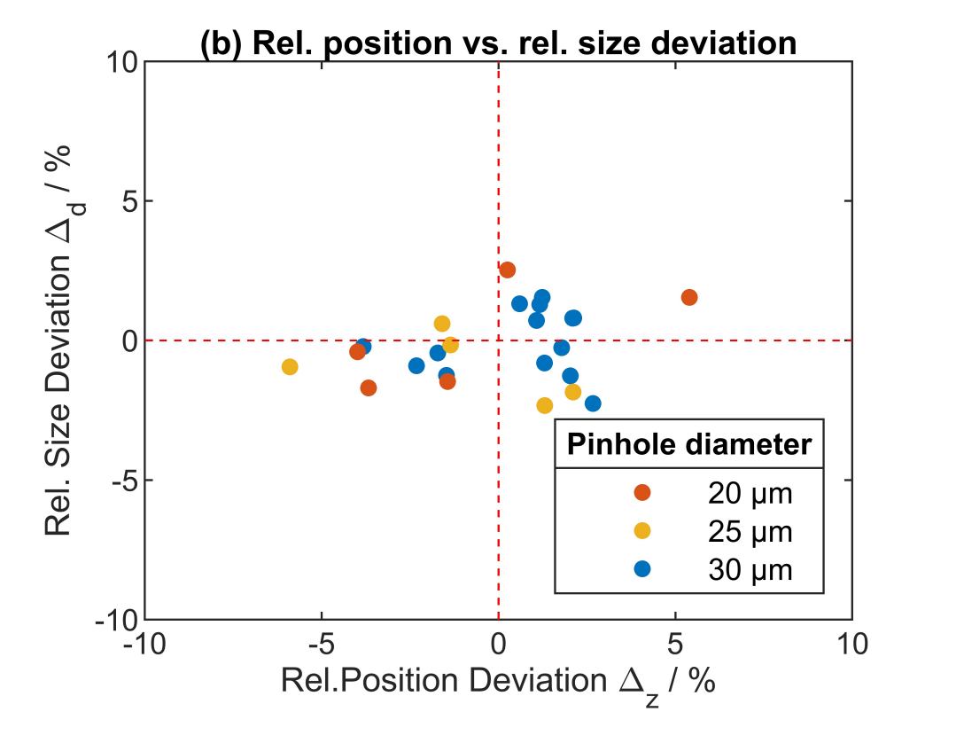
The Phase Doppler Profile Sensor (PDPS) combines the measuring principle of the LDV Profile Sensor for spatial resolved velocity measurements along a line with the Phase Doppler Technique for particle size determination. In a proof-of-concept the measurements are validated with a long-range high-speed microscope (HSM) and a droplet stream generator. The average deviations between the reference technique HSM and the new PDPS sensor are 0.4 % concerning the velocity, 2.2 % concerning the position and 1.1 % concerning the particle diameter (Figure 5 & 6). The PDPS system enables the simultaneous measurement of the droplet size and velocity distribution with low uncertainty.
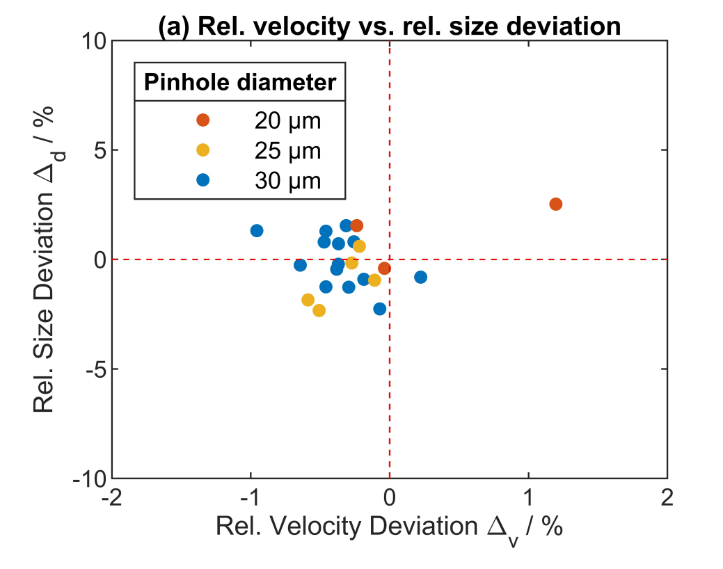
Fig. 5: Rel. velocity vs. rel. size deviation
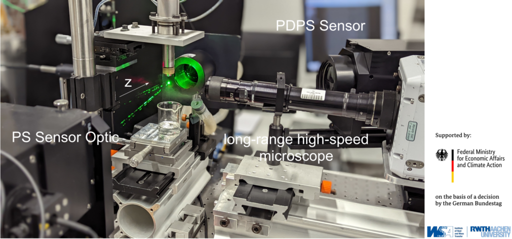
Fig. 7: PDPS Setup