DGV
Doppler Global Velocimetry (DGV)
Doppler Global Velocimetry (DGV) is a contactless and non-intrusive planar optical measuring method developed by the german aerospace center DLR. It is capable of determining three-dimensional velocity vectors in fluid flows. The preferred light source is a high power cw-Laser with a precisely adjustable wavelength. The Laser is used to create a light sheet with predefined height and width and with a homogenous intensity distribution over the entire cross-section. If a particle in the flow is illuminated by the laser the frequency of the scattered light is shifted by the doppler effect. The concept of the velocity measurement with DGV is to measure the doppler shift. The scattered light from seeding particles in the flow is focused on a detector (sCMOS chip) through a iodine cell. The transmission of the iodine is strongly depending on the frequency. The camera setup consists of a signal camera detecting the iodine filtered signal and a reference camera detecting the unfiltered signal form the scattered light. By measuring the filtered and the unfiltered light intensity the doppler shift can be determined.
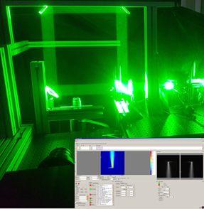
Fig. 1: DGV setup for the measurement in a heated free jet.
The ILA R&D DGV system, developed in cooperation with the DLR Cologne, offers a high spatial and time-related resolution and allow velocity measurements between 1 m/s and 3000 m/s. Due to the possibility of accumulating the light on the pixels even small particles can be used, especially for high velocities.
Figures 1 and 2 show the setup for a DGV measurement in a heated free jet. By measuring with one light sheet and one camera viewing direction only one velocity component can be acquired. To measure all three components of the velocity vector in the measurement plane the laser light sheet has to come successively from three different directions.
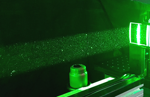
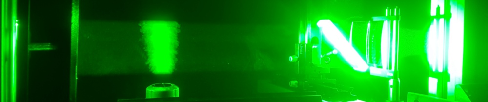
Fig. 2: Laser light sheet above a heated nozzle.
The ILA R&D DGV system consists of the high power laser source, a wavemeter, lightsheet optics, the DGV camera module (as seen in Fig. 3), the INDIO Controller and a DGV PC. All hardware signals come together in the INDIO Controller, which controls i.a. the wavelength, light sheet, laser power and iodine cell temperature. The hardware signals are incorporated in the ARES-Software which offers a comprehensible design, full control of all settings and easy-to-follow steps that are necessary for performing measurements (bottom right corner in Fig. 1).
The DGV hardware is very similar to the hardware used for FRS. So it is quite easy to update a DVG system for temperature measurements with FRS.
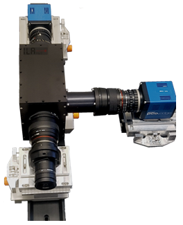
Fig. 3: DGV camera module with iodine filter.
Fig. 4 shows the comparison of DGV and LDV measurements at a free jet setup as shown in Fig. 2.
A second possibility to perform three component velocity measurements is the use of three different camera positions for one light sheet direction. Fig. 5 shows a setup with three camera modules. Because the lightsheet direction is not changing during the measurement the time resolution for this setup is higher and allows the investigation of unsteady flow phenomena.
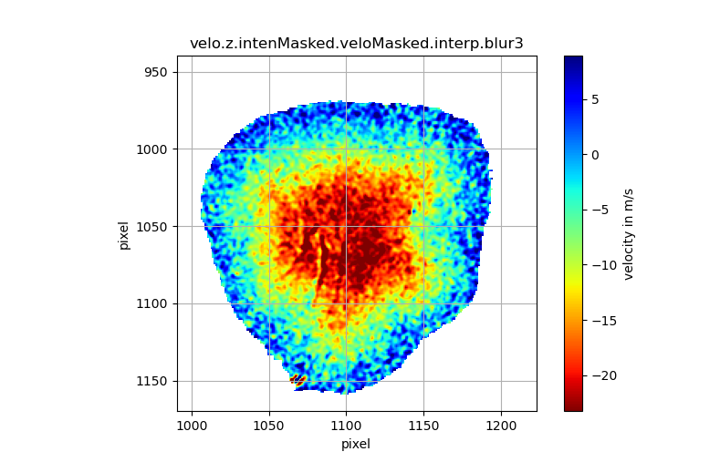
Fig. 7 presents the result of a 3 component DGV measurement in a free jet with the 3 camera module setup. The high velocity inside the centre and the steep gradient at the edge of the free jet is detected very well.
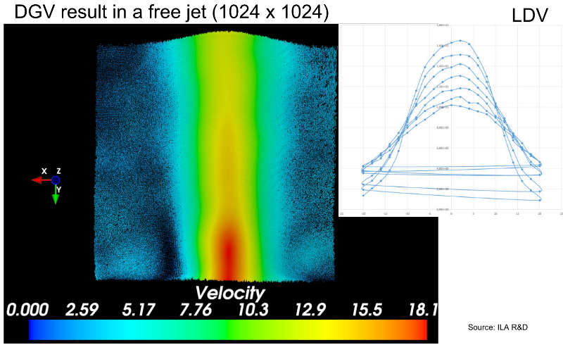
Fig. 4: DGV and LDV measurements on a free jet.
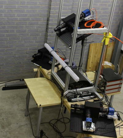
Fig. 5: DGV setup with three camera modules for time resolved measurements
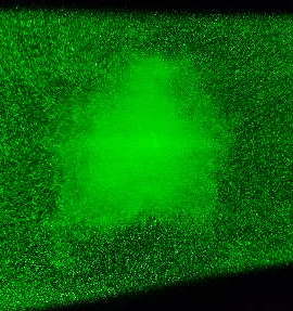
Fig. 6: lightsheet in a cross section of a free jet